Jay Fisher - Fine Custom Knives
New to the website? Start Here

"Bellatrix"
Whether you call it a shop or a studio, this is the place where all of the creativity and execution happens. It's a simple and yet sophisticated and sometimes complicated place, filled with equipment, supplies, and work areas. There isn't a spot that is unoccupied, not a place that doesn't have some critical purpose to the tradecraft and art.
Here, you won't see the typical layout of equipment and generalized photos that knifemakers typically post. If you've seen one knee mill, you've seen them all. If you've seen one belt grinder, you've pretty much got that part of knifemaking in perspective. What I'll try to do for those reading this is to give a deeper, closer perspective on my art and trade, with some insight into how, why, what, and where these individual compartmentalized tasks take place. You'll forgive me if I may, once or twice, boast about my studio; it's taken decades to put this all together and to make it all work, and it's the place I spend most of my time, year after year after year. The photos on this page can be enlarged by clicking on them, and there is no particular order to them so you can get an idea of the variety of work I do.
Someone once said that looking in my studio was like looking into my mind; I certainly hope that's not the case! My mind is much more organized, and hopefully more complex. Sometimes the studio is just a total mess, and I hope my brain isn't quite as casual!
I work hard to make sure that every device, component, machine, and part in the studio operates correctly, and continues to work, or there's no reason to have it. Parts must be stored, certainly, but they are support items critical to the dedicated device and machine and are not the focus of attention. There is always some machine, tool, or component that is down for repair, not quite working correctly, or needing an upgrade; this is the standard fare for most machine shops and artist's studios.
From my perspective, a knifemaker is not a simple worker; he's a technician, a craftsman, and, above all, an artist. If it's simple repetitive tasks that are performed, one might as well set up and program a machine to do them, for the human factor is not necessary. The shop then becomes the studio, where all is seen through the eyes of the artist and creator, including every piece of equipment, rack of storage, or station for dedicated tasks.
| 1. Milling a contact block heat exchanger | 2. Milling a contact block heat exchanger (2) | 3. Assembling a contact block heat exchanger | 4. A finished contact block heat exchanger |
| 5. Bluing knife blades and equipment | 6. Bluing knife blades and equipment (2) | 7. Anodization testing setup | 8. Anodizing cleaning process |
| 9. Layout | 10. Drilling retaining plates | 11. Disk grinding a tang | 12. Disk grinding a blade |
| 13. Surface grinding swarf | 14. Weighing bronze for casting | 15. Wood routers | 16. Cutting agate boulder |
| 17. Cutting agate boulder (2) | 18. Shop safety: buffers | 19. Internal metal bandsaw machinery | 20. Wax carving bench |
| 21. Morning moon setting | 22. Slabbing mookaite jasper | 23. Bolsters | 24. Wood sander upgrade |
| 25. Milling HULA parts | 26. Flashlight modification | 27. Ovens and Furnaces | 28. Knee mill controls |
| 29. Blades and ice crystals | 30. 28" Metal cutting bandsaw | 31. Flight Line, Cannon Air Force Base | 32. Compressor upgrade |
| 33. Welding Stands/Frames | 34. Lathe: boring aluminum block | 35. Milling/cutting rings (1) | 36. Milling/cutting rings (2) |
| 37. Sawing a blade blank | 38. Filework | 39. Young robin | 40. Drawing for engraving |
| 41. Profiling a knife blade (1) | 42. Profiling a knife blade (2) | 43. Profiling a knife blade (3) | 44. Profiling a knife blade (4) |
| 45. Indicating a hole depth on the lathe | 46. Bronze ingots | 47. Counterterrorism knife sheaths | 48. Wax model for casting |
| 49. Grinding a lead-in bevel | 50. Sunrise at Sharp Instinct Studio |

Milling is an active process. Mostly, you'll see photos of clean equipment; we all like to display our machines when they have been just detailed and look their best. It's kind of like combing your hair after you get up in the morning to look your best before the real work starts. Not many photos are flattering when you're grubby, hot, tired, and worn out, with dirty hands and stains on your clothing.
Everybody likes to look their best, but this is not how working machines look when they are in service; the photo to the right is how they look. The aluminum I've removed from the contact quenching block is substantial, and it takes several hours to clean up the mess. MRO suppliers sell guards and shields to try to contain the chip, but they just deflect it to somewhere else because they leave the block and the cutter at 280 surface feet per minute, which sends the lightweight chips flying, bouncing, and spraying out of the work. Even with a vacuum collector used in this cutting operation, this is the result! Add lubricant, which is necessary in all metal cutting operations, and the chip sticks to every surface it contacts.
It's important that the chips leave the cut; they are highly detrimental to the cutting operation. If they stay in the cut and contact the milling cutter, the heat and load created will fuse them to the block, load up the cutter, and overheat the cutter, possibly breaking it, but at the very least, dulling it and creating a rough, irregular cut. In order to drive the chips out and lubricate and cool the cutter, a special spray apparatus is used to spray coolant mist into the action.
This block is 2" thick and 9" by 18" in size. It's a heat exchanger, and the passageways are where the coolant flows during operation. The block will be covered with a thick plate sealed and secured by 60 machine screws. The purpose of this piece is to carry away heat during multiple pressure block quenching of knife blades, so that the aluminum remains at a fixed temperature for efficient and effective quenching.

Here's the contact block from the previous section after completed milling of galleries and drilling and tapping of cover holes. This is quite a piece of machined aluminum. Other knifemakers call these "plates" or "plate quenching" because they are usually using thin plates of aluminum, usually one inch thick or thinner. Since a large mass of aluminum is necessary for effective heat transfer, and since I needed enough thickness in the block for the coolant passageways of the heat exchanger, I chose thick, blocky 2" aluminum for this project.
You can see that the cover plate milling is inset .125" to accommodate the covers in the top left of the photograph. The machine screw holes had to be accurate for alignment, and evenly spaced and plentiful so that the unit could be sealed to prevent leakage.
At the bottom of the block, you can see two tapped holes near the ends; these are for the inlet and outlet piping. I chose 3/8"-14 National Pipe Thread for the fittings. In the very center, you can see a smaller hole for the thermocouple well that will accommodate a type K thermocouple.
In the upper right of the photo, you can see the end of the other block. The two holes are for the mounting brackets.
A lot of thought and consideration happens in the construction of a relatively simple device. I want to build it once and have it last as long as possible, for the rest of my life if possible. These block heat exchangers should do just that. I don't imagine I'll ever have to service or replace them.

The contact blocks, plans, fittings, thermocouples, cover plates and tubing for the project.
The plans for this project are hand-drawn, and though I could have putzed them up in Auto CADD, I chose to hand-draw them. On the plans, the blue highlighted areas are for the liquid pathways and galleries, and the pink area is the inset for the cover. You can make out the extensive list of numbers on the sides; these are the index and center location (X and Y) points for the milling and for all the screw cover holes.
The thermocouples can be seen coiled at the top center of the photo. The are type K, and stainless steel braided leads, stainless bodies, and stainless mounts assure permanence. They will be screwed into the aluminum blocks into the dead wells (not in contact with the liquid) with a heat transfer compound to assure that they will give a quick and efficient thermal indication of the center of the block temperature.
I used clear PVC tubing to make my connections. It's impermeable to most chemicals, remains flexible, and is see-through so I can verify flow through the recirculation system. It's also easily replaced if I have to. I'm not expecting a high heat in the coolant; this is the reason for the transfer in the first place, to move heat from the blocks. The covers will be secured into the blocks with stainless steel machine screws, with all passageways and dividers and screw holes sealed with RTV (room temperature vulcanizing) silicon sealant for a watertight seal. I'll pressure test the blocks at 20 PSI for leakage, even though they will only work at and experience atmospheric pressure in regular operation.

Here's the completed project, viewed from the back side. The frame of the device is in blue; it's a pivoting and balanced assembly that allows the heavy 2" thick aluminum blocks to be brought together evenly and flatly. It also has a lock built into the operation handle so that the upper block may be lifted and held in two positions above the lower block.
You can see the clear tubing enter the photo from the bottom left. It comes from the supply of a submersible pump in a container of treated water that resides inside the lower case (not visible in the photo). The control for the pump with overload protection is mounted on the left side of the case. The coolant goes through a 5 micron filter mounted to the heavy wooden base plate and then enters the upper right side of the upper block. The upper block is expected to see the most heat, so it gets cooled first. The coolant exits the upper block and goes into the lower block at the left side. It exits the lower block on the right side and returns to the coolant pump tank.
This device works extremely well. I created it because when block quenching thin blades, and quenching by a group will lead to high aluminum block temperatures. For instance, by the second block quenching, the aluminum can easily sink the heat and become over 150°F, which is too hot to effectively quench the next blade. In order to pull heat from the blades, the blocks need to keep as cool as possible, and in the future, I may even sub-zero chill the coolant if necessary! The aluminum transfers the heat readily, the coolant pulls the heat from the aluminum, and the thermal mass of the water-based coolant spreads out the heat from the blades so efficiently that after six blades, the aluminum blocks are only 1-2°F warmer than when I start!

In this photo, you can see the front or working side of the contact block assembly before I modified it with the heat exchangers. The opening is adjustable with two settings, and the blades can be quenched in succession, with operation by one hand on the large red knob at the handle on the left side.
The photo is a bit misleading, the assembly looks small but the blocks are actually 18" long by 9" wide and a 2" thick. This gives plenty of mass for block quenching, which pulls heat from the blades immediately, without danger of warpage from uneven transfer when quenching. The balance of the assembly assures even pressure from the top plate.
By the way, no device like this exists in any market, you cannot go to some machine supply outlet and purchase one. This is part of the tradecraft that a lot of people don't know about, having to design, create, troubleshoot, and perfect the machinery and devices necessary for this specialized field.

An important part of knifemaking is process. Here, the process is bluing. Bluing is deep oxidation of a steel surface, in order to impart a more passive surface that inhibits corrosion. A secondary effect is the color, which is black.
Only solid steel parts can be blued, and of a steel that is low in chromium, since chromium in significant amount (over 10%) becomes stainless steel, and bluing is not necessary, since high chromium steels are already resistant to corrosion. In knife blades, I only blue because of appearance. In other words, if someone wants a highly corrosion resistant blade, I'll always suggest one of the high chromium, high alloy martensitic stainless hypereutectoid alloys. But when a black blade is requested there is nothing quite as striking as a deeply blued blade of O1, high carbon, high tungsten and vanadium tool steel.
In this photo, you can see two blades hanging among the other stuff. What is the other stuff? It's shop equipment. Since a great deal of shop equipment is made of steel, and since it's not a stainless steel, corrosion can be an ongoing problem. In our location, the studio is cooled by evaporative cooling (swamp cooler), so this imparts a great deal of moisture into the air in the studio, keeping humidity high in the summer months. Without constant attention and oiling, all steel parts, components, devices, jigs, and equipment will readily rust. On the larger equipment, like milling and drill columns, lathe bedways, tables, and frames, I use a special set of rust preventatives to keep corrosion in check. But in small parts, this is just not reasonable. It's much more sensible is to blue them whenever I'm bluing some blades, because bluing means these steel components won't start corroding unless left absolutely wet! So this lightens the work load of long term and continuous maintenance on these numerous parts. Bluing also cuts the glare when using these fixtures, devices, and components under the bright lighting necessary in the machine shop/artist's studio.
In this photo, bluing is finished, and the parts have been dipped and washed in a special water displacing oil. The oil does just that, pushes any water used in the process away from the steel on a molecular level. Then, the items and blades are hung up to drain, cure, and age for 24 hours. This allows the newly blued surface to stabilize, and completes the process.

A photo of the completed parts and blades after bluing and curing. The knife blades are the most striking, since they are mirror polished before bluing and have a stunning appearance of black, wet glass. This is the same process that firearms are blued with, but you won't see a firearm with the appearance of these blades. This is because firearms, like most manufactured products, are never, ever finished to a polish. More likely, they are finished to a satin or blasted finish like the other parts in this photo, for a flat black look.
The other parts in the photo are jigs, small anvils, blocks and several small machine vises used to hold small parts for machining. While some of these are manufactured, some I make right here in the studio, since these specialized pieces of equipment are not available anywhere. One example is the ladder-like frame in the upper right of the photo. This is a Chicago screw head slotting vise, with special spring tension holding that allows me to finish and slot my special screws.

Anodization is an important part of the process of making superior aluminum knife sheath and accessory parts. Anodization is the process of applying electricity in a special chemical bath to aluminum (and some other metals) to affect a surface change. This process creates an extremely durable, near ceramic-hard surface on the aluminum, increasing wear resistance, increasing corrosion resistance, stabilizing the surface, and allows permanently dying it to a different color.
In this photo, the setup is for testing the process to work out the bugs and particulars of the line. You can see that it involves a lot of different chemical steps, involving immersion, heat, rinsing, timing, and electricity.
People are always a bit alarmed when they see electrical leads, measuring equipment, and power supplies with liquid chemicals, and rightly so! Not knowing what one is doing could be disastrous.
I credit my familiarity with chemical process to my youth, when I worked in a printed circuit board manufacturing plant as a chemical electroplating laboratory assistant. While only an assistant, I was exposed to a lot of process particulars, and this gave me a basis I would carry through my life. While the setup is crude in this photo, know that this is only a preliminary testing setup, and once the bugs were worked out, a more stable and permanent lab arrangement was made in the studio for this vital process. Maybe I'll include a photo of that later.

Starting the process of anodizing with deep cleaning. Oil, contamination, and organics are always a problem in metal surface treatment.
The surface of metal is active, no matter what type of metal used, and all vary in degrees of interaction with their environment. In order for process to be effective, it must start with a chemically, molecularly clean surface, inside and out.
Here, I'm using a strong alkali detergent at 190°F to chemically clean the 5052H32 corrosion resistant high strength aluminum alloy that will become the frame of my HULA (Holder, Universal, Lamp Accessory) that holds my tactical flashlights on my military and counterterrorism knives. Every bit of dirt, grease, oxide, every trace of oil, and even fingerprints must be removed and this caustic cleaner does the trick. It's in a stainless steel pot and suspended with specially made holders that will remain on the pieces throughout the process.

Individual components that are specifically made to exact sizes must be made in the studio. In this case, I'm laying out some fairly small parts. These are spring retainer plates for my locking combat waterproof sheaths, and they are less than .25" x .5". They'll have three holes, one for the spring pin, and two for mounting with small #2-56 machine screws. The material here is 304 stainless steel; it's very tough and highly corrosion resistant.
Layout is a specific skill that takes an understanding of geometry, machining action, and (of course) measurement. There are some great tools that didn't exist 30 years ago that can aid in this, but they are simply improvements on a ruler, measure, square, and compass (or divider) that have existed for millennia. Everything is an improvement on old arts.
I'm using a small centering punch and ball peen (machinist's) hammer to punch centers of all the holes. It's a heck of a lot easier to drill all the holes in the sheet metal before cutting and trimming the pieces.

Drilling the holes in sheet metal. Drilling is a fairly boring and common practice in machining, but requires a good understanding when small precision parts are being made. For instance, if I was concerned about exact tolerances, I wouldn't be using a back-up block of wood clamped in the cross vise on the drill; I'd be using a DRO (digital readout), brass or mild steel backup plate, starting each hole with a combination drill-countersink, the stock would be clamped down, and I'd be using a fixed column and auto-feed machine. But the level of precision of these pieces is not that critical, so speed is more important here since there are so many holes to drill. Each plate has three holes and one of them is a different size than the other two. You don't want to lose your place!
The reason the plate is curved is because I'm drilling so many holes and the drill bit is pressed into the sheet metal backed by a fairly soft wood. So each action of drilling is also forming, and slightly bending the sheet metal upward. No matter; the plate will be flattened and then all of the tiny plates will be trimmed apart.
By the way, there are 80 individual retainer plates in this sheet of 304SS.

The tang of a full tang knife needs to be flat. While the tang may be tapered on the flat platen of a belt grinder, that is not flat enough. Only a disk grinder has the capability of flattening enough for a precise fit with the bolsters and handle scales.
With the 60 grit paper shown, and the high rotational rate, you might be worried about my knuckles and fingertips. Rightly so, and gloves can't be worn or jigs or magnets used to hold the blade, because it's a sensitive and delicate procedure requiring a great deal of tactile control. But, for safety concerns, the worst that can happen is a badly skinned knuckle, and I've had a few.
The disk grinder is a specialized machine, even though most shops just consider it as a spinning piece of flat paper. This is far from the truth. The driving motor, in order to be truly effective, particularly in finer grits, needs to be variable speed, with serious torque control. This means that as the speed decreases and load is applied, the controller applies more current to keep the rotational speed constant. This is only possible with a DC (direct current) permanent magnet shunt wound motor. Motors that vary speed by varying current, frequency, or voltage do not have the capability to apply the high torque necessary at low speeds to keep the disk load constant, while keeping surging and harmonic vibration to a minimum. These DC drives are expensive motors and controllers, though they have gone down in price in the last 10 years due to magnet and manufacturing improvements.

The next issue for most grinders is the actual plate. Most plates are aluminum, and this is not good. If you're a maker, you probably don't want to hear this, but aluminum makes a lousy disk grinder, and the best are either cast iron or steel. These are not typical items, and will need to be made and balanced, particularly to fit the size necessary for most grinding.
What is that size? 8.75" in diameter. Why is that size important? Because it allows makers to use the 9" X 11" sheet abrasive that is offered in every conceivable grit size, density, backing, and abrasive media. Commonly called "sheet," this abrasive can be ceramic, aluminum oxide, silicon carbide, and even diamond.
There are lots of different grinding discs, but few variations of the actual abrasive sheet supplied for disk grinders, particularly in the standard sizes of 6", 10", and 12"! It is very difficult and expensive to find adhesive disks for this type of application any finer than 320 grit (40 micron), because in most of the applications of a disk grinder (either in a metal working machine shop or a woodworker's or plastics fabricating facility) there is usually no need for such fine grits. By using sheet abrasive, and cutting each sheet, you can get the abrasive and finish to do the job accurately and cleanly.
In this photo, I'm grinding the flat of a blade. The flat is seldom talked about but just as important as the hollow grind. The flat establishes the spine, the ricasso, and the lead off, and must be accurately ground side to side. I take my grinding through 9 steps to 2000 grit (5 micron) before polishing, and that keeps the grind lines crisp.
By the way, a paper cut by this spinning disk will certainly open your eyes!

Swarf is the fine metallic particles removed from an object in a machine shop, and in this case, the swarf is deposited from the surface grinder. The surface grinder is an important but often neglected tool, and is actually a very accurate machine, capable of removing material in absolutely flat fashion to a high degree of accuracy, about .001".
The blades are held on a magnetic chuck, and the table is moved back and forth (longitudinally and X-axis) and in and out (transverse and Y-axis) using hand wheels, while the grinding mechanism is moved vertically (Z-axis). Some larger surface grinders have automated movements which is a good idea if a lot of material has to be ground.
Most knifemakers modify their surface grinders to run with belts. This is because belts are efficient, and have wide and substantial grinding surfaces, and are readily available in the knife shop because they are used on the mainstay machine, the belt grinder.
Swarf is always a problem, as is all dust in the studio. While a dust collector was not used in this shot, it's a good idea to have some method of dust control on every machine. Constant cleaning and vacuuming has to accompany each operation, or the equipment and space becomes filthy, unworkable, and dangerous, not only from the standpoint of human hazards to respiration and fire protection, but to machinery surfaces, contacts, bearings, bushings and operating parts which don't respond well to insertion of clouds of fine metallic particles (swarf)!

Casting is the process of melting metal and pouring it into a mold. Bronze casting is probably the oldest, earliest casting process done by man, dating back literally thousands of years. In the studio, I cast knife stand components and independent artistic sculptural components in bronze.
In this photo, I'm weighing bronze casting shot for a casting of the wax model that is laying on the spiral notebook. The wax is first weighed, and then a calculation using a constant factor of ratio between wax and bronze gives me an accurate amount of bronze required to replace the same volume of wax in the mold. For a small casting like this one, the beam balance is a useful tool for measuring this.
Bronze casting for knife related objects falls between jewelry casting (typically much smaller) and sculptural works casting (typically larger), and this size realm makes it challenging to come up with the process components suited to this range. Like so much of the studio, I have to adapt one type of process to my particular needs.
As I get older, I'm casting more and more sculptural pieces for the knives. Metalwork, in all forms, has and always will be a focus of my creative arts, and it continues to captivate. Like this photo represents, record, calculation, and process variables must be considered and guided for desired results. In this case, the models create a mold that becomes the bronze cabochon retainer on my Lycaon sword, specifically, the ring of leaves that surrounds and holds the agate moon on the ricasso of this sword.

I haven't gone deeply into the woodworking part of my studio on other pages of the site, but you can get an idea that I do work a lot with various woods not only from my Wood Knife Handles page, but also on my Stands and Cases page.
Woodworking is an important part of what I do, and this is no better demonstrated than in some of the stands and cases I make for my knives. I love woodworking, just as much as knifemaking, and have made plenty of wood projects in my life.
Wood working tools start as simply as the various hand saws you see hanging on the wall in this photo, and you can also make out the wood lathe tools on the wall at the upper left of the photo. The photo features three routers I find indispensible in the studio, and they vary greatly in size, scope, and power. The big three horsepower DeWalt is frequently mounted underneath this specialized router table I made many years ago, and the tiny Proxxon is a great diminutive router for small detail work and tiny, accurate cuts. The old Craftsman in the middle is a great all-around performer.
The table I've adapted for the extremely high accuracy of Incra brand fence and components, you can see them some of them in the central hole of the table. These are sophisticated alignment devices, clearly capable of machine tool accuracies, down to .001" in wood!

Lapidary is an intensive effort in my studio. Just know that I make more gemstone handled knives than any other singular knifemaker in the world, and you'll get an idea of how important and critical lapidary is in my art.
Rock is stubborn, obstinate, and refractory. It's extremely hard, tough and unpredictable. The difficulty of working with large chunks of rock keeps people from making large items of any gemstone, apart from very soft stones like alabaster and marble. While I do use some marbles, they are the tougher and harder variety.
Gemstone handles start with a saw. Here you can see a piece of rough rock in the vise of the saw, ready for blocking, followed by slabbing. Orientation is a critical part of choosing the best face of any rock, and if slabs (slices) are needed, this must be chosen carefully. Not all rock looks good from all angles.
Rock doesn't look impressive when its in the rough. The surface is flat, non-reflective and can be oxidized by thousands or millions of years of exposure to the elements. You can see the oxidation on this piece of stone on the same face that the tape is. It's dirty looking, boring, and you can barely tell that it's green. Fresh breaks are always brighter, and wetting the surface can help to visualize what the finished surface will look like.

Perhaps you were wondering what kind of rock is in the previous photo, so I'll give you a greater description. This is a 78 pound boulder of Indian Green Moss Agate gemstone. Technically, any rock that is larger than 10" in dimensions is a boulder. You can see by the ruler how large this boulder is. The saw blade that will be blocking the agate is 24" inches in diameter. It runs under special mineral oil coolant, a wild flood of spray that must be contained in an entirely covered machine. The vise that clamps the rock will advance, extremely slowly, as the diamond-tipped saw literally abrades its way through the rock. This is a very, very difficult rock to cut, due to its extremely high hardness and the overall size of the piece.
Having a 78 pound bolder delivered brings joy to my UPS driver. Thankfully, they didn't ship it postal, as this nearly outweighs our delivery person! It's funny when the delivery people ask, "What do you have in here, rocks?" And I simply smile and nod affirmatively.
Indian green moss agate comes from India, and it's a regularly exported rock by that country. It is, like all true agates, a cryptocrystalline (microscopically crystalline) form of silicon dioxide. Agate is translucent chalcedony, and often shows layered growth, sometimes concentric. It has a vitreous (glasslike) luster, and is a 7 on the Mohs scale, with a density of 2.65. The Indian green moss agate varies greatly in appearance depending on the cut. To see this gemstone on a knife handle, take a look at this "Achelous" dagger.

Safety in the shop and studio is a constant focus. I keep this glove tacked to the wall to remind me to wear my gloves when buffing blades.
The buffers are, by far, the most dangerous power tools in knifemaking. They are essentially spinning rags moving up to 150 miles an hour. Several knifemakers have been killed by the buffers, and many more injured. High speed buffers demand respect. They will, in a moment, grab the exposed edge of a blade and pull it from your hands, travelling around the wheel and direct it back at your hand. I don't buff knives that have cutting edges, so this accident happened with just the tip of the knife (dull) glancing by. I was wearing a glove, but it wasn't sufficient to stop the penetration of the unsharpened point and the result was a significant slice. Don't click on this photo link of my injury if you are squeamish.
We learn from these accidents, and my lesson is that now, I wear penetration resistant Kevlar and leather gloves in buffing, with Kevlar and leather gauntlets to protect my forearms. I also regularly wear a heavy leather apron, and of course a respirator and eye protection while in the buffing room.
There are significant changes and improvements a maker can initiate in his buffer setup to vastly improve safety, and the most important one is to orient the buffers so that the operator can not physically stand perpendicular to the axis of the wheel, because if a blade is to fly, that is the direction it will go. In buffers where this is not possible, full guards and a tight access will substantially increase the safety of the machine.

When people look at machine tools, they typically only consider what they can see, but this is just part of the machine. Here, I've removed the cover from my 28" throat, 2 horsepower band saw, for maintenance and inspection.
Band saws are one of the most important pieces of machine shop equipment; the very first operation performed on a piece of metal or wood is usually done by the saw. I know of many makers who simply detest sawing, and try to find ways to work around this critical step, like having dozens of blades cut out by an outside company using water jet. When it comes to smaller pieces of metal, like bolsters, guards, and fittings, they opt for eliminating them altogether, just because sawing them out and machining them to fit the knives is so much work.
My attitude is to learn to improve and love what necessary tasks are most difficult. That way, they are no longer obstacles, but beneficial! In doing so, they become pleasurable, and appreciated much more. It took weeks to modify this band saw to operate specifically for the knife shop, and maybe I'll go into that in another section, but no modifications were done to the drive system you see here.
The three phase, 2 horsepower electric motor drives a small air pump to push chips from the blade, and drives a variable diameter, variable speed pulley that is changed by operating the large horizontal screw with an exterior hand wheel. The pulley drives a jackshaft on the main center mount, which drives a chain that drives the four speed transmission (in green). The transmission drives the main wheels at the base of the machine. All of this machinery has to be regularly cleaned, inspected, and lubricated for smooth operation.

Wax carving is an important part of casting. The wax is the model, and can be created a variety of ways, but all ways mean that in some parts of the process, wax will have to be carved and worked.
The waxes used for high detail work are not what most people consider wax, which is candle wax or paraffin. These are microcrystalline waxes, very tough, very dense, with relatively high melting points. They are capable of rendering a model in extremely high detail when used with the right casting mold material (the investment). So high is the detail that you can literally cast a fingerprint in the surface and it will be visible on the surface of the cast metal!
It takes a lot of different types of wax for successful modeling, including lower temperature types for vents and sprues. These waxes can be identified by their color, but not always.
The bench in this photo seems a mess, and there is no actual model in the photo. I wanted to demonstrate how many tools and components are needed to simply create a very small piece, and how all of those are in very close proximity on the bench for easy reach. Most of the tooling can be identified, like the files and hand carvers, file card, and rotary tools. The device with the wires and the panel is a wax carving console, adapted from the dental industry for carving waxes for implants and stuff the dentists need. We owe a lot to the dental trade in lost wax casting; the high detail waxes and investment as well as tools we as sculptors and jewelers use come from their science and industry!

Out of the window of the shop/studio, the moon sets early in the morning over Dennis Chavez park and pond. Living in close proximity to the park is interesting, and for the most part, pleasant. The state stocks the pond with rainbow trout and large catfish, and there are even programs in our state to catch the largest.
People don't often think of fishing when they think of New Mexico; they think instead of vast desert lands, and you might be surprised to know that there are no Saguaro cacti anywhere in New Mexico, at least not naturally. People also commonly confuse us with Texas; New Mexico has mountains and ski areas; Texas does not. They confuse us with Arizona which has the well-known Monument Valley's singular isolated monolithic mesas, and New Mexico does not. People are surprised to know that the largest cheese producing plant in the North American continent resides about 15 miles from my studio, in the great dairy lands of Eastern New Mexico where I grew up and currently live. Really!
New Mexico has plenty of wild lands, and an impressive diversity of waters. Our game and fish department stocks 2 million fish annually, including largemouth and smallmouth bass, walleye, white bass, catfish, bluegills, perch, and pike, and have established or reintroduced native Rio Grande cutthroat trout, Gila trout, Kokanee salmon and tiger Muskie! We also have Brook Trout, Brown Trout, Lake Trout, and Rainbow Trout.
The word Clovis is well-known (particularly among archaeologists) for Clovis man and the Pleistocene Clovis culture dating back over 13,000 years. One of the oldest occupations and kill sites of wooly Columbian mammoth, ancient bison, camel, horse, sabertooth cat, sloths, and dire wolf megafauna. The Paleo-Indians were here because there was a big watering hole, a low collection point for water in the vast sea of flat grassland we call the Llano Estacado (or staked plains). It's humbling to think that many millennia ago, some Paleo-Indians were making knives and points using rocks, and running down and killing giant beasts with them mounted on sticks... yeah, we've got it pretty good now. If you want to know more about this reach into the distant past, put the term "Blackwater Draw No. 1" into any search engine.
The landforms where I live can be classified as stark. From General Randolph Marcy, in a survey in 1852: "When we were upon the high table-land, a view presented itself as boundless as the ocean. Not a tree, shrub, or any other object, either animate or inanimate, relieved the dreary monotony of the prospect; it was a vast-illimitable expanse of desert prairie .... the great Sahara of North America. it is a region almost as vast and trackless as the ocean -- a land where no man, either savage or civilized permanently abides ... a treeless, desolate waste of uninhabitable solitude, which always has been, and must continue uninhabited forever."
He would be surprised to see the endless dairies, miles of agriculture in cotton, corn, sorghum, wheat, and cattle, cheese plant and production facilities, Air Force base, wind turbines, and people who live here now!

Slabbing rough gemstone boulders and cobbles is an important part of the process of acquiring and using gemstone and rock for knife handles. Most makers who attempt and use stone start with a slab, and someone else, usually a lapidary or rock shop, has already done the slabbing for them. Then they can just look at the pattern and decide whether or not to buy the slab.
As a lapidary, I prefer to do my own slabbing, if at all possible, for the gem I use for handles. This allows me to orient the rock in the saw, and match and control the pieces that I use for the handles.
Mookaite jasper is a very hard, very tough rock from Mooka Station in Western Australia. It is technically a chert. Chert is a microcrystalline or cryptocrystalline sedimentary rock material composed of silicon dioxide (SiO2). It occurs as nodules, concretionary masses and as layered deposits. Chert breaks with a conchoidal fracture, often producing very sharp edges. So this jasper could be used to make spear points, and it's certainly tough enough! This chert is not just a sedimentary rock, it's also a fossil, made of billions upon billions of radiolaria, or radiozoa, which are protozoa from the Cambrian period, about 500 million years ago. These deposit of their remains formed into muddy silt, and their remains and the remains of other creatures were replaced by silicate-bearing minerals that give the striking colors and patterns. The sediment fossil was then subjected to geological process, further changing the structures. This is a beautiful rock and takes a stunning, glassy polish. Knives I've used this material on are the Macha and the the Bulldog. Seeing this photo makes me want to make another knife with Mookaite, and it's an addiction I enjoy!

Bolsters offer a tremendous advantage to the durability, shape, strength, and longevity of a knife. It's sad that most makers nowadays, as well as most knife manufacturers, will try anything to not have to bolster a knife. They avoid bolsters because it's a tremendous amount of work, and for no other reason, no matter what you may read or hear. They don't want to hassle with making them, matching them, and mounting them, so they simply don't, and then they come up with creative reasons why they don't bolster knives. History has shown us for hundreds of years how important these little pieces of additional metal are on the knife, and we certainly have the means and equipment nowadays to make them. I write about bolsters in great depth on my Knife Fittings Page.
In this photo, I'm preparing to mount bolsters on 11 knives. The bolsters are all 304 high nickel, high chromium austenitic stainless steel, a tremendously tough and durable stainless used to make stainless nuts, bolts, and fasteners. You can see that the bolsters are pinned; on larger knives with larger bolsters, there are three or four pins, on smaller knives there are two per bolster. The pins are 1/8" (.125") and are also 304SS.
Pinning and peening is the absolute toughest way to mount bolsters, and requires more skill than you might think. Blades and bolsters are drilled to exactly the same size as the pins, and I don't use any tapered holes or other gimmicks to mount these. While welding may be stronger, it will create a HAZ (Heat Affected Zone) that would destroy the hardness and temper of the blade. The method I use creates an extremely strong mounting arrangement that strengthens the knife overall, and absolutely will not come off or fail, ever. To remove bolsters mounted in this fashion, they literally have to be ground away. Pins are peened until they swell throughout the bolster and blade, and become invisible at the surface. This takes a lot of hammer forging skill, and most guys think they are pretty good with a hammer until they try this application. There is a test for hammer dexterity; perhaps I'll include that later.
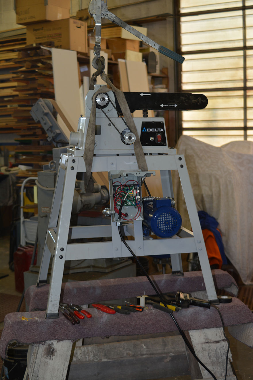
Sanders for woodwork are marvelous inventions. They can speed up finishing work, square up pieces, and with the dedicated tables, can accurately apply angles for joinery. Unfortunately, since nearly all machinery is now made overseas, mostly in China, they also leave a lot to be desired. The brand Delta was started by an American, in Milwaukee in 1919, and the brand was bought by Rockwell in 1945. In 1981, the brand was bought by Pentair (now owned by Black and Decker), and it was at about that time (the early 1980s) that the manufacturing started moving offshore and the quality went sour. I don't know the exact date, but the point is that when these companies start moving manufacturing offshore, the price stays the same, but the quality nose-dives. This was, in essence, a poor piece of unfinished equipment, and when I would turn it on, it ran at such a high speed that all it would do is burn up the wood. It would vibrate, shudder, and the balance was so bad that the machine would literally dance across the floor, causing me to hold it down with my foot! The electric motor was entirely open, with exposed windings and armature, which is absolutely ludicrous for a sander that generates wood dust. The control circuit used a mechanical momentary two-step switch to engage first the start winding, and then that would disengage and the run winding would kick in. Of course, the switch for this was a complicated but poorly made affair, and the dust generated meant it didn't last long. But, all in all, the price was right, and that's the point of Chinese-made machines.
In essence the frame of the machine was serviceable, so I removed the motor and turned and installed a jackshaft of 4140 steel with the appropriate bearings, along with a drive pulley. I changed the internal open winding motor to an enclosed 125 volt, Direct Current (DC) permanent magnet motor (in blue). This motor is controlled by a modern control system, which allows me to vary speed, torque, minimum speed, starting voltage, and all of the critical functions of the motor. You might think that a simple on-off switch would work, but like most machinery, fine control will yield much better results. In the photo, I'm making the electrical modifications. You can see all the various electrical tools resting on the sawhorse: pliers, wire strippers, cutters, screwdrivers, soldering iron, solder, and tape. The electrical box keeps dust out of the circuit board. The speed control is right next to the start-stop switch.
I'm very happy with the sander now. Though the drive and control system cost more than the entire unit, I can't be happier with the result.

Accessories are an important part of the assembly or ensemble of a tactical, rescue, military, counterterrorism, law enforcement, or professional's knife package. My clients who want the finest tactical knives don't just want the knife; they want an entire assembly of options. This typically starts with an assortment of sheaths and also the accessories they request.
Accessories for the modern custom knife are wholly and completely neglected by other makers and all manufacturers. When you ask them what accessories they make, they'll tell you that they make the sheath, considering it an accessory! This is terrible; the sheath is part of the knife, not an accessory! The professional who wears the knife into combat needs a dedicated sheath, perhaps several, and nearly always requests accessories for the sheath.
Years ago, I started answering these requests by creating effective, integral accessories for my knives and sheaths, and the HULA is one of those accessories. The Holder,Universal, Lamp, Articulating (HULA) accommodates high quality programmable flashlights by mounting solidly and permanently to a sheath, and allows the lamp to be aimed and positioned in any direction, freeing the hands of the user. This simple device is not made by any outside company or source; I make them right here in the studio, and every one is made individually by hand. This is because they are extremely tough, made of stainless steel and high strength corrosion resistant aluminum alloy, and nobody else wants to bother to go through the trouble of making them!
In this photo, I'm working up a batch of them, a dozen or so, and have formed and welded the front and rear cups and am milling the centers to be completely concentric and to hold the specific flashlight they will accommodate. More about HULAs

I started adding flashlights to my tactical knife assemblies and packages quite a few years ago. I did this (and still do!) because typically, people who use my tactical knives will, at some point, need the minimum of a flashlight in their duty, business, profession, explorations, and travelling. It could be that they are out later at night than they expected, and need a simple aid to get back to camp/home. It could be that they need to look in a hole, a dark place, or examine something that requires more light during stormy times, dusk or dawn, or just a heavily shaded location. If they are emergency medical professionals, a flashlight is critical for diagnostics and examination. In rescues, they are simply indispensible. A small light, typically known as a keychain or penlight, is the first necessity, followed by a larger, heavier lamp. At a minimum, this is why I offer the solitaire.
Before modern LED (Light Emitting Diode) technology, lamps used xenon-filament bulbs. These are standard improvements over argon-nitrogen gas filled tungsten element bulbs, in that being filled with xenon gas makes them last longer. But they are simply nothing compared to the modern LEDs. I like the Maglite Solitaire for my small flashlight accessories, and years ago, they didn't make them with LEDs, so here is a modification I did on those early models for comparison. The xenon filament lamp is at the top, the LED at the bottom, along with the bulb and parts modification. Not long after I started doing this, Maglite started manufacturing the LED lamps in the Solitaire, so this shows how ahead of the curve my clients demands are!
The LED Solitaires are a huge success; even clients who don't want to go full bore for the HULA assemblies usually want the Solitaires. I mount them in dedicated sleeves in my UBLX (Ultimate Belt Loop Extender) or my LIMA (Lamp, Independent Mount Assembly) that work with my tactical sheath systems. More about my sheath accessories on this page.

While people who are unfamiliar with the heat treating process of knifemaking might think that all knifemakers work with a glowing, roaring forge, the highest quality and most sophisticated treatment of these metals happens in a metal box. In several reality show interviews I've had, the producers were flatly bored with this concept, and chose to take their projects to guys who hammer hot metal for effect. They need color, light, motion, and wild activity. They need drama, defeat, and conflict. They aren't interested in how some of the most modern, high technology tool steels are treated for some of the top counterterrorism units in the world, who demand the very best possible blades. There really is no television interest in staring at a metal box that is automatically controlling all the stages of the process.
But this clearly is how the very best steels are treated, with tight, accurate, and specific control of the environment. This means not only controlling the temperature (rate of change, set point, and timing) but the atmosphere itself. In the photo from left to right, you can see the high pressure nitrogen/argon purging bottle and regulator, the large burnout oven/furnace with powered exhaust vent on the top, the smaller silver-gray tempering/utility oven, and below that the blue sword furnace. Below that and behind the rolling drawer cart is an older heat treating furnace awaiting repair, and in the center is a workhorse firebrick-faced furnace. To the extreme right is a large and substantial tempering/utility stainless steel drying oven, laboratory grade. Below is storage and supplies to run all these beasts. The power panel that feeds them is substantial, and it helps to have a 250 Amp, 240 Volt, Three Phase feed to my shop and studio. This is only the heating side of the process, the cooling and cryogenic components are not pictured here, they are immediately to the left and out of the frame. More about Heat Treating and Cryogenic Processing of Knife Blade Steels.

Controls are an important part of the machining and knifemaking process. I'm grateful to have the background of an industrial electrician; this allows me a refined methodology in setting up, improving, and refining the control mechanism for the hundreds of machines in the studio. I don't change them all, just many of them, and I'll probably continue to refine, adjust, add, and change the control systems on all of them until I die! This is because evolution is the key to keeping up the business and operational aspects of what I do.
The photo at the right is of the control package for my Bridgeport knee milling machine. While the mill is a standard fixture in all small and large machine shops, what you see here is not. It's an evolved hybridized approach, a common theme that you'll see repeated as this page and discovery goes on. I've converted the milling machine drive system to all direct current, which is a much more efficient, powerful, robust, and economical way to drive the machine. At the top of the photo is a VA meter, measuring voltage and overall amperage of the incoming feed to the machine, so that I know how much juice is being used to feed it, so I can regulate and adjust loading depending on what the machine is being used for. Below that is the main box of the DC controller, which controls speed, direction, and even brakes the mill so you don't need to use the hand brake (yes, there is a hand brake on the milling machine to aid in speedy tool changes). Mounted on the front of the controller is the RPM/SFPM tachometer, which measures and indicates both rotational speed and the surface speed of the cutter or device. Alongside is the X-Y DRO (Digital Read Out) which indicates the absolute position of the cutter in relationship to the table. This device alone would fill a book on its capabilities, and (of course) I'd like to upgrade it to a X-Y-Z DRO in the future!

Most people think of steel: forming, machining, and the creative process as being based in heat, not cold. The physics of change is really what this art, craft, and science of metallurgy is based on, and being able to accurately, regularly, and successfully initiate change in this very special material (steel) is the very root of what I do. As I stated in my bio, I started because I was fascinated with heat treating and the results.
Heat is a relative term, though we base our knowledge, understanding, and manipulation of this material on our own reference point, which is room temperature. Of course, one can only imagine what happens elsewhere in the universe, where the base temperatures are not what we consider comfortable. In relation to heat is what we consider cold, and it's all just a scale of difference, a range of energy of the material and surrounding that we can choose to manipulate. Taking a piece of powder metal tool steel from room temperature to over 1900°F (1035°C) and then down to -325°F (-200°C) in a matter of several hours is quite a range of operation and quite a bit of change occurs!
The photo is about a 7 power enlargement of some serrations on a CPM154CM powder metal technology high molybdenum martensitic stainless steel hypereutectoid tool steel blade, after hardening and a 40 hour soak in deep cryogenic range. It's warming up to room temperature, and after it warms a while, it reaches the condensation range of the moisture in the air, so ice crystals start to grow and form on the steel. These are tenuous, feathery structures that only last a few minutes before melting and disappearing. More about Heat Treating and Cryogenic Processing of Knife Blade Steels.

Cutting metal is an extremely important part of the entire knifemaking process. Because I make so many different designs and patterns of knives in so many sizes, with so many metal parts and fittings, the saw becomes more than a tool that blocks out material. The evolution of the bandsaw becomes an art form and skill set all to its own.
What do I mean by this? First, a powerful enough, robust enough piece of professional equipment is built on a heavy cast iron frame, and this one weighs in at a over a ton. I ordered it with some critical features, like a 28" throat (the distance between the blade and column, and the absolute maximum width that it will accommodate there). I also specified a power table, one that drives the cast iron table along under the blade. It also came with a blade welder, a tremendously important accessory that can be used to weld all my bandsaw blades in the studio.
I spend weeks "tricking it out" or rather, refining the critical functions that were not quite suited to my needs. I installed a power (Volt-Amp) meter to gauge the load on the saw. I installed a control circuit that it didn't have, which allowed me to disconnect all of the electrical controls and feed some additional accessories. I installed under-column LED lighting, and added several features to the table. First, an additional on-off illuminated button set allows me to control the saw from the table rather than reaching up to the column continually. You can see the green and red buttons on top of the table control box. I also moved the table direction switch, which was non-intuitive, and installed a quick-reverse jog button to back the saw out of the cut at its highest speed. I installed an indicator meter set (the gray box at the top right of the saw frame) that allows me to know and set the voltage and current of the table feed before I even start the cut. You can see a bright red line that is the laser I installed that projects an accurate bright red line on the material exactly where it will be cut. I made custom clamps, accessory clamping tables, and holding fixtures to grip all kinds of material rigidly secured to the table. I even made custom handles on the clamps with quick-spin rigs and a special wrench to make for speedy changes and adjustments to the clamping set. There are also special hangers and tool holders on the back for blades and equipment used for this machine. On the front you can see the yellow speed-feed chart and the clipped strip of paper that shows exactly what blade is currently in use.
All of these changes took additional design, wiring, adjustment of the schematics, circuits, feeds, controls and accessories. Having a basis as an industrial electrician means this is fun work for me, and the result is a saw that, with care, will cut out thousands of blades, bolsters, and accessory metal parts for longer than I'll be alive. As I stated above in the section that shows the internal machinery of this saw, many makers and fabricators detest sawing. By making some critical adjustments to a good piece of equipment, sawing becomes a pleasure that I sincerely look forward to!
I received this inquiry: "Why don't you use water jet or plasma cutter to cut blanks? Doesn't seem like it would effect the final product, and you do enough hand work already, using band saw seems like gilding the lily, unless there is a reason."
This is a good question, since many makers and nearly all businesses are looking to quickly blank out knife blades as fast as possible. Here's my personal experience:
I make many, many different styles and patterns of knives. Currently, I have over 500 individual patterns, and at least a dozen more are awaiting my photography so that I can include them on the patterns page. Because I make so many patterns, it's a bit ridiculous to have to submit these to a company that water jets the blades. I like to start on a knife, do everything myself, and have complete control over the process without having to wait for any outside contractor. This leaves everything in my control, and like my Heat Treating, means that I can tailor each individual aspect of the task to each individual project.
Most knifemakers have limited equipment. They are using Portabands®, horizontal cutoff saws standing upright, saws without speed control, or saws that are just too small and not up to the effort. Because of this, cutting out blades becomes a tedious, frustrating affair. Some of them are even using abrasive cut-off wheels on angle-head grinders, and it's no wonder that blanking out stock is a sore spot!
I learned early on that this was something I had to tackle head-on, thus the saw you see above. It's very fast, it's always ready, and I actually look forward to cutting out knife blades, bolsters, parts, and metal for jigs, jobs, and equipment upgrades and repair. With the bandsaw detailed in this very topic, and the two other bandsaws in the studio, cutting out blades is not a long, arduous affair, and you might be surprised at how fast and easy I can cut out a blade.
Now, about plasma cutting. This should never be done on any knife blade, or any steel that has any significant alloy content. This is because the heat from the torch creates a HAZ (Heat Affected Zone). This is an area where detrimental changes occur in the alloy. In knife blades, this would be along the cutting edge, or at the tip, or around the butt, or around the profile where filework and edge refining must occur. Sure, it can be ground away, but a significant portion must be ground away to get to the "good stuff" where the HAZ ends and that is not always a certain defined point. This will mean using larger, wider stock, and an extra rough grinding step on an air-hardened edge. There will be an uncertain alloy and microstructure at that edge, and it's just not worth the hassle or uncertainty when a bandsaw is how most machinists handle raw stock. These bandsaws exist for a reason, and I'm grateful for this one!

I do get out of the shop, and sometimes it's a real pleasure. This is a photo of the flight line of Cannon Air Force Base in Clovis, New Mexico. It was taken early in the morning, just after sunrise, looking east. We had a good rain the night before and I can almost smell the fresh, crisp air in my mind.
It's been a huge honor to make knives for our United States Air Force Pararescuemen, and now, particularly for our Special Tactics Squadrons. When I took this photo, I was on my way to present one of these knives to our unsung heroes, guys who put their very life on the line to save others in combat and rescue.
You can learn more about my work with them on several dedicated pages on this website: my USAF Pararescue Knives page, and the PJLT knife page.
Here are a few links to knives I've made for pararescuemen and combat controllers.

The air compressor plays an extremely important role in the studio. It supplies clean, clear, dry air at 125 pounds per square inch throughout the facility, driving everything from the sandblaster to the engraver, from the chip blowers to the lubricated hand tool manifold. It supplies the power drawbar on the mill; it drives the rotary air tool for carving wax models for bronze casting. It's a tool that few consider, but is a work amplifier that no modern studio can do without.
This is a photo of the compressor upgrade I did several years ago in the studio. The old compressor is on the right; it still worked okay, but could become taxed when doing heavy blasting while other air tools were in operation. It was starting to leak a bit around the rings and valves, and is a single stage unit that would get fairly hot in continual operation. The heat means more fluid and condensation in the line, and a heavier current draw as the motor has to work harder to keep up. Plus, the technology of the old unit was dated and less efficient than the newer one.
The new one is a good bit of beast. It possesses the most powerful electric motor in the studio, 7 horsepower, and I'm lucky to have three phase power available. It has mid-stage cooler, and a hefty aftercooler that helps tremendously with load and condensation. It's a two stage affair, and can surpass the bored-out blaster even with the valves at full open! In the photo, I'm getting ready to move out the old one and make my connections to the manifold and new wiring.

What a mess! How could anyone work in this nightmare? This is how real world welding looks, unfortunately, at least in my studio. The floor is cluttered with cables, cords, hoses, and equipment. The hood and grinder give an indication of the work, and the bottles, racks and clutter have a definite purpose! And it all gets cleaned up afterward.
In this photo, I'm fabricating a rolling stand for my sword oven (in blue in the doorway) and other heat treating and tempering ovens you've seen in the section above. This is a very tight area to be working in, and I would ordinarily be outside, but it was raining. Few people think of how critical support and arrangement is for shop equipment and operations. I try to keep it manageable, yet wide ranging in scope, and that leads to a conflict of space. Consequently, rolling equipment is the standard, so that these heavy frames are necessary. The frame will also include storage for all the necessary related supplies and equipment of the process, something seldom considered when one looks at the individual equipment. Though you may not know it from this photo, I've become a master at arranging equipment and space; fitting as much into an area as is humanly possible!
Strength is also critical in all these hand-built stands, tables, and racks. Some of this equipment is robust and weighty. You might notice a bit of color here and on the linked oven photo. I'm an artist; why paint everything gray? By the way the purple table has the centrifugal casting machine, the electro melt furnace, and vacuum pump and investment tools below.

The bench lathe in the studio is a fairly substantial player. Though it's called a "bench" lathe, this doesn't mean it sits on a bench, because it weighs about a thousand pounds after all. This lathe has plenty of power; it can twist off a two inch diameter steel bar with plenty of torque, via a heavily geared transmission. This is one of four lathes in the studio, and the largest.
While this lathe doesn't perform much of the actual knifemaking process, it's used for plenty of other support. I use it to create my accessories for the tactical knives, tooling, setups, and hardware. Here, I'm milling the bore of a block of aluminum that will become a new contact wheel for the belt grinder. Yes, I make my own contact wheels.
The 2" thick 6061 aluminum block is clamped in the four jaw chuck, and the center is located. The bore will be created first, and then the work is clamped in the bore for the external cutting. Toolmaking is an important adjunct to the operation, as custom tools for the knifemaker are simply not manufactured. In this way, the creative process of machinist intertwines with the knifemaker; one discipline allows the other to flourish. Kind of heady stuff when simply boring a block of aluminum...

There are many ways to make a finger-sized hole in steel, but to make a large hole in very tough, moderately hard steel stock used for knife blades can be a time consuming affair.
In the old days, I would drill these holes. This was no easy task. The final dimension would need to be 1" in diameter or larger, a pretty big hole. The way to do this on a standard drill press is to first locate and punch the center, then drill a starter hole with a combination drill/countersink or a spotting drill. This is followed with a pass through of a drill about 1/4" in diameter, and then a pass with a 1/2" diameter drill. The reason to drill with successively larger drill bits is because the web of the drill bit (the absolute center core) does not cut, it simply scrapes and at a relatively low speed. When it gets to larger bits, that web is pretty big, and it takes plenty of force to displace the metal; thus, multi-step drilling. But the final bit is really big, and most drill presses won't accommodate this size of drill bit. So the large drilling is best done on a milling machine (or knee mill), which has the torque and power to literally drive the table into the bit. But still, this takes multiple setups, and no fine tuning of the size of the bit or the final hole is possible. This is why currently, I've moved to my Pantographic Engraving and Die Sinking Milling Machine to do this work. Note that the pattern that controls the hole size is on the right table (called the Copy table), and the work is clamped to an aluminum tooling plate on the left table (or work table). The movement of the spindle (and cutter) is done with the horizontal shiny handle on the copy table, with a copy bar following the template beneath it. More in the next photo below.

Continued from the previous section, here is a closer view of the setup. The copy table and guide to the right is slightly out of focus due to the limited depth of field on the camera (low light) but I think you can get the idea.
The copy bar rests in a circle template made of high density fiberboard (hardboard) that is carefully sized for a variety of circle sizes. You can make out the writing on each that lets me know what the resultant size will be depending on the copy bar size and the cutter size and the reduction ratio. Here, the pantograph is working on a reduction ratio of two. The milling cutter is a solid carbide mill, and it cuts away the ring a little at a time as I continue passes using the template as the guide, and I raise the work table. Though this seems a bit slow, it is not, and I can actually do the setup and complete ring cutting in a fraction of the time it would take me to do the same task with drills, simply because there are no tool changes necessary.
An added benefit is that I can set the size of the ring to any dimension I like. Since drill bits are fairly standard sized and limited, I don't have to buy special bits if a guy wears heavy gloves, for instance; I can just adjust the hole larger. This is a fast, versatile, and dependable setup and surprisingly accurate, given the condition and maintenance of the machine tool. It's guided all by hand, using feed pressure, rate of cut, advancement of cut, all controlled by hand.
A machinist might consider a boring tool, or an annular ring cutter, or a fly cutter for such a job, but these tools have inherent chatter that is difficult to eliminate on these very tough steels. With this setup, I'm only cutting a ring, not the entire hole, and the milling cutter is stable and relatively small.

The transition from a design to a pattern to a template to a blade physically happens at the saw. Since I work mostly with extremely high alloy hypereutectoid tool steels, these cannot be forged but must be cut from bar stock or billets. The saw is a special tool, and many makers ignore the importance of this critical piece of machinery. They look for the fastest, easiest way to get things done, and may send out steel to have it cut by water jet, plasma, or other blanking operations. Since I make so many different patterns of knives, sawing is critical in the constant stream of knives.
This is the clamping arrangement and guiding that I've developed for my bandsaw, featured above. The laser line tells me exactly where the cut will be, and the rigid cast iron clamps and cast iron table secure the blade to the table. The table travels slowly, and the blade is a special type, a bimetal blade of M42 high speed steel cutting teeth, bonded with a more flexible backing steel that transfers the force between the saw's contact wheels and the work. The blade is sophisticated, with variable pitch and wavy kerf for minimizing vibration. I don't use any lubricants on the blade. The reason is that they would only offer marginal help, while wetting and soiling the contact wheels that drive the blade, causing slippage and excessive wear. Saws that are used this way for this type of material should run slowly and be of sufficient blade length to not overheat any one particular tooth. That is why it's critical that the blade be long, so the tooth has more time to cool than to heat up. How long is it? Over 13 feet!

Filework was probably started as a way to create more purchase and grip on a slick knife blade or spine, but evolved into a decorative art form. Some people think that it's a recent development, but the Italians and the Scotts were doing this in the 1600s.
When it's done by machine, it's called "jimping." Jimping and filework are very different, and calling filework jimping is an insult, but hobbyist knifemakers do it all the time. I suppose it's just lazy slang, but the distinction is that filework, good filework, must be done by hand. It clearly and specifically distinguishes the knife as handmade, and like other forms of hand-created metal embellishment (like hand-engraving) clearly sets knife value apart from machine made copies. Because filework is distinctive (like engraving) to the artist who does it, it also distinguishes the style of the piece, at the artist's own hand.
Filework is done before the knife blade is heat treated, as a file can not cut a hardened blade. There can be no grinding, sanding, or adjustment of filework after the blade is hardened and tempered, and that's why a lot of inexperienced makers don't do it. If they fudge, slip, or make an error in grinding or finishing of the blade, the filework can be destroyed, or at the least, damaged enough to look bad, ruining the blade. Completing a fileworked blade while preserving these sometimes delicate cuts can be a difficult and careful affair. Metal can't be ground away, and like hand-engraving, only a thousandth to three thousandths of an inch (the thickness of a sheet of paper) can be ground away in finishing before the filework shows a distorted and bad geometry. More about filework on my "Embellishment" page.

A young robin perched on the bars at one of my shop windows. He's curious, new to this world, and wonders why human beings spend time in buildings, facilities, and are busy at tasks when they could simply browse the yard for worms and seeds and late summer berries.
This is a juvenile; he/she has not developed the full reddish chest and has a pale orange with mottled black breast. You can see the pinfeathers and new plumage on his head.
Robins are common here, as are many birds. It's great to hear their songs early in the morning in springtime, and not so great to have them clean off all your ripened grapes from the vine in the fall.
Being a robin is a hard, short life. Most don't make the first year. Luckily, in our area there is plenty to feed on; endless grasses, berries, fruit, and nuts. And then there are the farmer's fields full of sorghum, wheat, and grain, and plenty of insects, too. There are worse places to be a bird.

Engravings on knife blades start with drawing. Each artist has his own method of drawing, and if the maker is also the engraving artist, the piece will, by necessity, flow from the singular concept and ideas of one artist. The piece takes on a depth of uniformity, rather than a work that's been "embellished." It's the way I choose to have my work created.
The technical part of drawing, pattern, and arrangement is, or should be integrated with the artistic style of the piece. Here, the blade is finished to 1200 grit on the flats and hollow grinds, and the blade is fully fileworked. The steel has not been heat treated, and will be engraved in the fully annealed and spheroidized condition. This necessitates rather good control of heat treating process, as finishing the blade by removing more than a thousandth of an inch (.001") will destroy the engraving.
The design work is done at about a two to three power enlargement of size, and you can see how the knife pattern was divided up and reassembled to fit the size of the paper in sections. Lots of hand-drawing, adjusting, erasing, redrawing, and inking going on here. I prefer bold patterns, kind of my style, that go with the design of the knife overall. The pattern of this blade is my popular Helicon-Horrocks, or Helhor. When this is finished, you'll see it posted on the website, and it will be a very bold piece.

The knifemaker is almost wedded to his belt grinder. Truly, this is the most versatile machine possible for such work. It's fairly simple, a belt (typically 6' or 72" long and 2" wide) is driven by a drive wheel on an electric motor. The belt can run anywhere from zero to 9000 feet per minute, or up to about 100 miles per hour. The high speed is typically not necessary, unless you're doing things like profiling a knife blade, and hogging out large amounts of material.
When new makers get started the first relatively large expense they will need to be productive is the belt grinder. Over the decades, I've seen makers try to fabricate these from found pulleys, scavenged motors, and bits and pieces of lawnmower parts (I'm not kidding). While there have been some minor advances of new grinders, the technology of this machine remains very simple. The belt moves, around and around, and when profiling blades, to give you an idea of the speed, this six foot belt makes 12 revolutions- in a second!
One thing a lot of new belt grinders are missing is the safety equipment. Full guards, front, sides and back, are often left out of these new grinders and kits. So the dust, swarf, and burning metal is spewed in a hopeless disc of scatter away from the machine in every direction, a fire and health hazard that does the maker, his facility, and his shop/studio no good. The thing is going to make dust, and the best that you can do is to restrict the dust to the very close proximity of the work, and pull it away and into storage or out of the building with a substantial dust collector (not a vacuum cleaner). This is what the "box" is below the wheel.
I'm going to go on a little here about this photo. You can see in the lower left corner of the photo a big red paddle button that is marked "off." This is the grinder control. Usually, the control box is mounted above and behind of the machine so that the dust it creates does not destroy the electronics. It's a good idea to have the stop switch very close at hand in case of emergencies. You'll notice also the garb of your favorite knifemaker. Heavy clothing, an apron, and a do-rag, are all cotton. This is because cotton won't propagate flame like nylon, polyester, or other manmade fibers. Note the half-mask respirator. More than a dust mask, it's a chemical cartridge filter that can block organic solvents, vapors, or other dangerous chemicals that may become airborne, as well as all fine particulates. The safety glasses are heavy framed and plastic lens types, but there are no gloves. While this may seem counter intuitive, gloves would remove the fine sensitivity needed to accurately grind blades. This may not matter much in profiling, but when grinding, gloves don't work. Note in the background another grinder; a production knifemaker needs several of these machines for various setups.

A closer view of the belt grinding at work. Here, I'm using a tool rest, a relatively small piece of cast iron, as a table to support the blade. The blade has been cut out on the bandsaw, and the excess metal is ground away down to the scribed profile line. You might ask if the steel gets hot. Yes, it does, but not as fast as you might think. Steel is a relatively poor conductor of heat, particularly when compared to silver, copper, and aluminum. When grinding aluminum, the metal instantly gets the same temperature as where it's contacting the work, a noticeable difference.
The profiled edge is not perpendicular to the blade flat. This is because the wheel is round, and at this geometry, the blade will be slightly wider at the bottom than the top. More on that below.
The wheel being used here is a special high durometer (high hardness) rubber wheel with serrations around the proximity. You can't see them because the wheel is spinning so fast, but the serrations allow air to circulate between the wheel and belt, and allow higher point concentration of force in various positions of the belt at each revolution. This means a much more aggressive cutting action. Serrated wheels are only used to rough or hog metal, and they have high vibration, and irregular cutting action.

After the blade is hogged close to the profile and the scribed line, it's important to go over the grind to make it perpendicular to the blade flat. This allows a more accurate shaping, grinding, and finishing of the entire blade, particularly the periphery. There are a lot of technical reasons for this, and I'll probably detail them in my book, but what is important is establishing a square, accurate profile at this point.
This is done with a flat platen on the belt grinder. The platen is simply a cast iron face (plate) with two contact wheels aligned at both ends (or top and bottom) to force the belt to slide along the plate. While it seems flat enough for this kind of operation, many makers use flat platens to accomplish the entire grind of the knife, to establish a bevel grind, narrowing toward the cutting edge. This is such a common practice that it's accepted in knifemaking as "normal," when it's creating what I consider a markedly inferior grind geometry, in all but the very thinnest knife blades, typically less than 1/16" (.0625" or 2mm). I go into it in detail on my "Blades" page at this bookmark, but the idea is that no matter how low of an angle, a flat grind will quickly become too thick after three sharpenings of the blade, and the cutting edge angle will require a bunch of metal to be removed to reestablish a sharp cutting edge. But it's easy to flat grind so that is why many inexperienced makers do it. History has shown us time and again that the sharpest, longest lasting aggressive cutting blades are hollow ground and the link above shows why.

Here, I'm using a horizontally mounted belt grinder to profile the inside of the tang of the handle of the knife, and specifically to form the profile for the finger groove.
One of the great advantages of a well-designed belt grinder is the ability to use a wide variety of contact wheels. This one is only 3/4" (.75" or about 2cm) in diameter. The cutting action is extremely aggressive, and it's critical that the belt be run at a very low speed. If not, the surface feet per minute of the belt will over-speed the small bearings of the contact wheel and burn them up. The 3" guide wheel behind the cutting wheel (and closest to the camera in this photo) allows a very tight radius of the belt and access to deep cutting in a profile.
A lot of makers put tool rests on horizontal grinders, and they do it because it helps them keep the grind square an perpendicular. I've practiced so long with so many (thousands) of blades that that's not an issue. The drawback of the tool rest is that it will force the work to be done on only one small area of the 2" wide belt, right above the where the flat tool rest plate sits. This will wear out a grinding belt in a hurry. When grinding offhand, though taking plenty of skill and practice, the hand can move up and down the belt, utilizing all of the abrasive surface, shortening the cutting time, lowering the point contact heat, and lengthening the belt life. There is a definite technique to keeping this cut perpendicular, and again, I'll probably go into it in my book.

Measurement is always a tricky affair on machine tools. The reason it's tricky is because nearly every job is different, nearly every setup is different, every machine tool is different, and every measuring device is different. Add to that just a slip of a tool and a measuring device is damaged, like the plastic front face lens of this dial indicator on my small lathe.
The setup is simple: accurately measure the depth of a hole drilled in a round stainless steel pin on the lathe. A piece of squared aluminum stock is clamped to the neck of the tailpiece arbor, and the dial indicator is magnetically clamped to the tool base. The drill chuck in the tailpiece is advanced, and the depth of the hole is indicated.
This is a rough, temporary setup, and I don't use it anymore; I've developed another method. I just included this to show some of the details that have to happen in these prototyping and tool-making operations. By the way, I replaced that cracked lens on the dial indicator.
What was I making? I don't even remember; probably a part for tooling, like a tap extension or holding arbor for another tool, a tool used to make a combat sheath or accessory, or folding knife part, or something I needed. And this goes on continually in the studio. Toolmaking is a part of knifemaking, as the machinist knifemaker is continually making tools, parts, jigs, and setup devices to do another job with regularity, control, and accuracy.

Materials are a wonderful thing, and as a knifemaker/artist/sculptor, I use plenty of different kinds. These are ingots of silicon bronze, and I'm cutting them into "brownies" that will be used for my bronze castings.
I cast bronze mainly for the stands of the artistic knives. As my work evolved, bronze became the premium material to permanently express my sculptural intent in the knife arrangements, and in the artwork overall. I've started out making knife stands in stone, antler, wood, and even acrylic, but as I evolved in my work, I've added bronze. Bronze is the metal of the ancients, our first metal of creation, and has a deep history and value as an artistic medium. It's extremely long-lived, very tough and durable, and richly elegant and beautiful.
The ingots are rough, they weigh about 20 lbs. a piece, and have to be chopped into manageable sizes for weighing and placement in the melting furnace crucibles.
When you first see the golden-colored ingots, your mind naturally turns to gold; this desire is built-in, mainly through our culture and history. The astounding thing is that while each of these ingots weigh 20 pounds in bronze, the same ingots in gold would weigh over 51 pounds! Gold is incredibly heavy, and in our popular media, you'll often see actors in movies and shows throwing gold bars around with easy abandon. Nothing is farther from the truth, as gold is 1.7 times the weight of lead. Imagine putting three or four gold bars into a gym duffle, and having it weight more than a person... you don't see that in Hollywood. And actors are never as tall as they seem in the movies either!

Building knife sheaths for actual counterterrorism knife users is a very involved affair, particularly when they are one of the top counterterrorism units in the world. It's a great honor to make these knives and sheaths, and have them evaluated, used, and depended upon for counterterrorism operations. I write about this in depth on my Counterterrorism Knives page.
My military and CT clients demand the most durable, functional, and sometimes elaborate sheath assemblies possible. They need them to function flawlessly, with adaptive arrangements and mountings that interface with a variety of equipment they may have depending on the specific mission. In this photo, I'm building a group of sheaths with their accessories.
While it looks like a mess, it's all very clear to me. The knife that each sheath is being made for is grouped with the sheath, as are all the belt loops, footman's loops, horizontal belt loop plates, LIMA, and HULA lamp accessories. The plastic trays (actually lids) contain the associated stainless steel hardware and fittings for each unit.
There are never enough benches in the studio. Real estate is at a premium here, and a flat workbench will always be covered with a project. It then becomes paramount that everything has a final resting place, a home, so that after a job like this is done, all those necessary small bits and pieces and tools can find their own home and the bench can be cleared for the next project(s). As the studio evolves, storage and organization becomes a critical and vital operational aspect. Most people don't realize how organization of a facility can mean functional progress, or crippling failure and time wasting, as tools are misplaced, scattered, or mis-associated. What I mean by mis-associated is being used for another task, and not available in the room or current task at hand.
One of the neatest compliments one visitor to the shop gave was unusual. She took a look around and claimed, "What organization!" Of course, all I could see is that I needed to vacuum the floor...

This is a wax model of a fairly complex item I was casting. I created this as a test, to see what investment vehicle worked best, and on a particularly finicky metal, 5052 corrosion resistant high strength aluminum alloy. This is not a typical casting aluminum, and not often cast to any volume.
The actual object being cast is in the dark blue wax. The red wax rods are the heavier sprues, and the light blue wax rods are the vents. The molten metal will flow into the mold in the area where my fingers are holding it, and distribute through the tree of sprues into the model chamber. The displaced air will go up the small vent tubes and allow the metal to fill the cavity.
This actual test was a partial failure. The model did not fail, neither did my sprue and vent arrangement, but rather the investment mixture I created the mold with. And it really wasn't the mixture; it was the fact that I should have given it about three times the lower temperature cure time and a much lower rate of increase in heat, as the mold split from being heated too fast by water expansion in the drying phase.
Most people have no idea that a lot of experimentation, evaluation, adaptation, tuning, and testing goes into this kind of artistic endeavor. It's not unusual to invest days, even weeks into a object creation to have if fail, and have to start over. That's knives, sheaths, stands, and even the website, as I've tried a lot of things along the way. I know my clients appreciate it all, so I keep trying, growing, and learning.

Grinding a knife blade is a common task in the knifemaker's studio and shop, and before grinding the hollows in the blade, a short bevel of material should be taken off the cutting edge so that the belts are preserved by not having to encounter an extremely sharp angle of steel that would strip abrasives off the belt. So the lead-in bevel is created with an old, worn belt to change this geometry. The old belt is a bad cutter; it creates plenty of heat, and then plenty of spark, which is burning pieces of metal flying through the air and contacting a lot of free oxygen, continuing the burn.
In this rather old shot, you can see a bucket of water below the grinder to catch this spark, but you also may notice that a lot of it is flying into my apron. This will burn a hole in it eventually, and a lot of knifemakers have holy aprons in their shops.
I use a much better system now; I use a special tool rest that has a hole in it right where the sparks are flying, and a heavy dust collection system below the wheel to carry it all away.
A funny point is that on at least one video on YouTube, you can see a knifemaker "demonstrating" his pride and joy of a belt grinder to some interested visitors in his shop. They want to see just how great the grinder is, so he grabs a chunk of titanium and hogs it into the wheel, which creates a tremendous shower of white sparks, like an outdoor fireworks display on the forth of July. I've done this too, and it's just for effect, a blatant call for attention.
The reason I write this is because titanium is best ground on an extremely slow speed, with a high feed and pressure rate. Otherwise, it instantly work-hardens, and creates excessive heat, forcing excessive pressure, and thus the white-hot sparks-'a-flying. So anytime you see someone grinding with white streams of hot embers rocketing around the grinder, it's done for effect only, to impress the locals. Otherwise, grinding titanium is a boring affair, with little show and boring visuals.

This is a shot of the sky during sunrise several years ago. The studio looks like a small building, but it's a long structure, with a small front facing the street.
It looks a lot different now; different sign, trees covering the front, and the old little truck is long gone. So are the signs from the front; in fact, most people can't tell it's a business at all. I made it this way because I don't do any local business; I rarely even sell a knife in my state (New Mexico). This is because I have clients all over the world. I don't encourage locals coming to the door looking for someone to sharpen their knives.
I actually did, years ago; sharpening knives was a good addition to some income when times were lean. Every new or young maker should have to do this; it trains him in knives that other people have and use, and teaches him not only to sharpen, but to deal with clients face-to-face and learn a little about their lives.
When I was young, I was volunteer firefighter for many years, and an Emergency Medical Technician. This taught me a lot about people's personal struggles, emergencies and plights, and gave me a lot of respect for life, and what others are going through. If I could encourage one thing in our youth, it would be to spend some years in the volunteer service to others, to give them an understanding of humanity on its basic and caring level.
I've limited this page to 50 photos, but am building another page to post the next 50. Check back to see that page posted as well! Thanks for taking the time to be here, and learning just a bit about my studio, shop, and workspace. Thanks most to my clients who have requested this page, and honored me with the support that allows me to do what I love!

| Main | Purchase | Tactical | Specific Types | Technical | More |
| Home Page | Where's My Knife, Jay? | Current Tactical Knives for Sale | The Awe of the Blade | Knife Patterns | My Photography |
| Website Overview | Current Knives for Sale | Tactical, Combat Knife Portal | Museum Pieces | Knife Pattern Alphabetic List | Photographic Services |
| My Mission | Current Tactical Knives for Sale | All Tactical, Combat Knives | Investment, Collector's Knives | Copyright and Knives | Photographic Images |
| The Finest Knives and You | Current Chef's Knives for Sale | Counterterrorism Knives | Daggers | Knife Anatomy | |
| Featured Knives: Page One | Pre-Order Knives in Progress | Professional, Military Commemoratives | Swords | Custom Knives | |
| Featured Knives: Page Two | USAF Pararescue Knives | Folding Knives | Modern Knifemaking Technology | My Writing | |
| Featured Knives: Page Three | My Knife Prices | USAF Pararescue "PJ- Light" | Chef's Knives | Factory vs. Handmade Knives | First Novel |
| Featured Knives: Older/Early | How To Order | 27th Air Force Special Operations | Food Safety, Kitchen, Chef's Knives | Six Distinctions of Fine Knives | Second Novel |
| Email Jay Fisher | Purchase Finished Knives | Khukris: Combat, Survival, Art | Hunting Knives | Knife Styles | Knife Book |
| Contact, Locate Jay Fisher | Order Custom Knives | Serrations | Working Knives | Jay's Internet Stats | |
| FAQs | Knife Sales Policy | Grip Styles, Hand Sizing | Khukris | The 3000th Term | Videos |
| Current, Recent Works, Events | Bank Transfers | Concealed Carry and Knives | Skeletonized Knives | Best Knife Information and Learning About Knives | |
| Client's News and Info | Custom Knife Design Fee | Military Knife Care | Serrations | Cities of the Knife | Links |
| Who Is Jay Fisher? | Delivery Times | The Best Combat Locking Sheath | Knife Sheaths | Knife Maker's Marks | |
| Testimonials, Letters and Emails | My Shipping Method | Knife Stands and Cases | How to Care for Custom Knives | Site Table of Contents | |
| Top 22 Reasons to Buy | Business of Knifemaking | Tactical Knife Sheath Accessories | Handles, Bolsters, Guards | Knife Making Instruction | |
| My Knifemaking History | Professional Knife Consultant | Loops, Plates, Straps | Knife Handles: Gemstone | Larger Monitors and Knife Photos | |
| What I Do And Don't Do | Belt Loop Extenders-UBLX, EXBLX | Gemstone Alphabetic List | New Materials | ||
| CD ROM Archive | Independent Lamp Accessory-LIMA | Knife Handles: Woods | Knife Shop/Studio, Page 1 | ||
| Publications, Publicity | Universal Main Lamp Holder-HULA | Knife Handles: Horn, Bone, Ivory | Knife Shop/Studio, Page 2 | ||
| My Curriculum Vitae | Sternum Harness | Knife Handles: Manmade Materials | |||
| Funny Letters and Emails, Pg. 1 | Blades and Steels | Sharpeners, Lanyards | Knife Embellishment | ||
| Funny Letters and Emails, Pg. 2 | Blades | Bags, Cases, Duffles, Gear | |||
| Funny Letters and Emails, Pg. 3 | Knife Blade Testing | Modular Sheath Systems | |||
| Funny Letters and Emails, Pg. 4 | 440C: A Love/Hate Affair | PSD Principle Security Detail Sheaths | |||
| Funny Letters and Emails, Pg. 5 | ATS-34: Chrome/Moly Tough | ||||
| Funny Letters and Emails, Pg. 6 | D2: Wear Resistance King | ||||
| Funny Letters and Emails, Pg. 7 | O1: Oil Hardened Blued Beauty | ||||
| The Curious Case of the "Sandia" |
Elasticity, Stiffness, Stress, and Strain in Knife Blades |
||||
| The Sword, the Veil, the Legend |
Heat Treating and Cryogenic Processing of Knife Blade Steels |
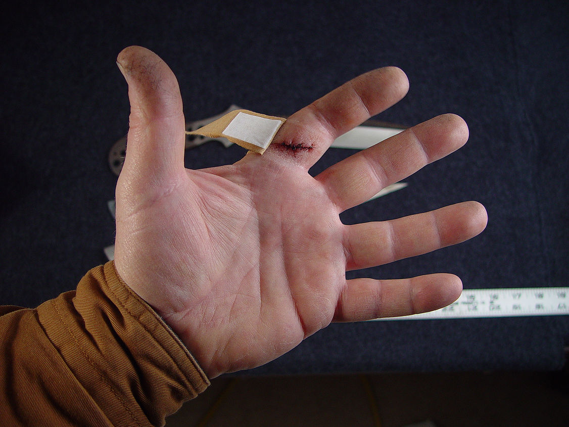